The Scanning Electron Microscope (SEM) is widely used in various fields of industry and science since it is one of the most versatile imaging and measurement instruments. SEMs allow users to see details 1,000 times smaller than those obtained using conventional microscopy. On the downside, images provided by SEMs are only two-dimensional. Over the last few years, thanks to on-going research carried out by the Mountains® development team, several possibilities have been made available to SEM users for switching from standard 2D images to “topographic” images.
Shape from motion vs shape from shading
The most metrologically accurate approach to 3D reconstruction of surface features is stereophotogrammetry. This technique requires two SEM images of the same object taken from two different angles. Height information is calculated trigonometrically. Subject to good experimental conditions, the method gives accurate values. However, its drawback is obviously that it requires tilting the specimen and taking two successive images of the same area, which may not always be easy, e.g. for a wafer.
The most common alternative to stereophotogrammetry (“shape from motion”) is reflectometry (“shape from shading”). The principle uses the intensity of electron reflection on the surface to assess local slope, then compiles local slopes into a complete topography map.
How does shape from shading work?
In the picture below (left) taken from space of Meteor Crater, Arizona, we can see that the left part of the crater rim appears light, almost white, whereas the right side is dark. This is obviously because the sunlight is coming from the right. One slope is lighter in color because it is inclined towards the sun, the other is darker because it is inclined away from the sun. This gives us information on slope. Moving in a path from the left of the picture to the right, a light pixel will mean “crater height decreases” and a dark pixel “height increases”.
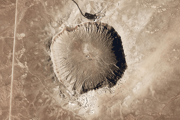
Above: Meteor Crater, Arizona seen from space.
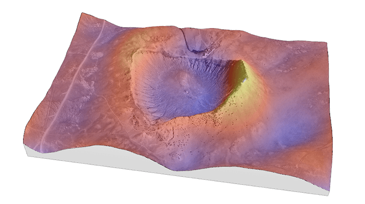
Above: 3D reconstruction from this single image obtained using Mountains® software.
This aerial view, with the sunlight coming in from the side, is equivalent, in terms of illumination, to the electron gun of an SEM operating from above with the electron detector placed to one side of the specimen.
Now, if we compile data from across the entire image, we can build a 3D representation of the meteor crater.
This representation is not perfect however :
Rim height is overestimated in one direction (left-right). This is because we can differentiate increase or decrease in slope in relation to the direction light is coming from, but not perpendicular to this. If light is coming from the east, west-east slopes are detected, but north-south slopes are not. This highlights the need to work successively in two orthogonal directions, to make height assessment in both directions possible.
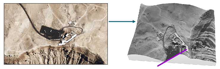
At the top of the picture, we can see the visitor center (white) and the road and car park (black). In the 3D reconstruction, these are obviously misinterpreted as slopes (see the slope of the car park in the image below):
So what’s the solution?
Using a four-quadrant detector will help clear away both of those two issues.
A four-quadrant BSE detector is a ring detector that surrounds the electron beam path. The ring is divided into four quarters. 3D reconstruction in this case, contrary to the stereo method which requires two successive images taken at different tilt angles, can be obtained with only one scan (the four images are acquired simultaneously).
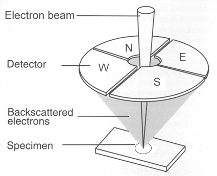
Above: diagram representing four-quadrant BSE detector.
Detectors work in pairs
To assess slope in one direction (e.g. west-east), two opposite detectors are used. This allows us to overcome the albedo (car park) issue. If the object is locally darker or brighter, both detectors see the same. It is the differential signal between the two detectors that allows us to distinguish a darker area from a slope and therefore correctly calculate slope.
There are two couples of opposite detectors : one specializing in east-west slopes and the other in south-north slopes. Nano-meteor crater topography rebuilt from four four-quadrant images would exhibit homogeneous rim height (not just a high rim on the left and right).
Once slopes in both directions have been correctly detected, they can be integrated into the surface topography and will yield outstanding 3D images. This is something Mountains® is very good at doing. And very quick too (calculations achieved in less than a second).
In the image below, a 3D view has been generated using Mountains® from four BSE images obtained simultaneously. We can see that the software is able to reconstruct heights homogeneously regardless of direction. It is also capable of distinguishing different kinds of material inclusions: dark regions and actual holes or even holes with inclusions inside them.
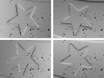
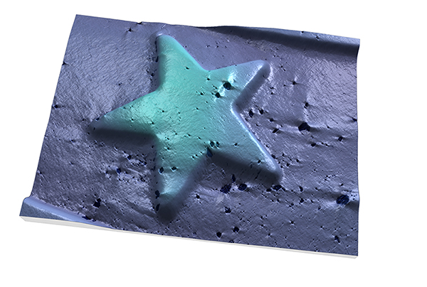
Above left: a detail of a 1 euro coin scanned using a Hitachi scanning electron microscope equipped with a four-quadrant detector, resulting in four images of the same area. Right: 3D reconstruction using Mountains® software.
Nowadays most SEMs are delivered with a pre-installed multiple-angle BSE detector. Generally, this is a four-quadrant detector (detectors at 90°). In the case of Thermo Fisher Scientific (formerly FEI), it is a three-segment detector (120°). Whatever kind of multiple image detector your SEM possesses, Mountains® has a solution for 3D reconstruction. And seeing the software is now provided by most SEM manufacturers with their instruments, as standard or as an option, why not upgrade your images to 3D now?
You may also be interested in:
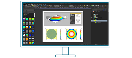
Try Mountains® surface analysis software for free
Author : Christophe Mignot
Resources :
Meteor Crater: en.wikipedia.org/wiki/Meteor_Crater